In Part 2, I covered how to upload a vSAN Witness Appliance into a vCloud Air Organizational Catalog. This process doesn’t require any specific networking to be in place, other than connectivity to vCloud Air directly.
Networking in vCloud Air
In vCloud Air, multiple independent networks can be created with visibility across different Virtual Applications (vApps), Virtual Data Centers (vDCs), and sites external to vCloud Air. Some of the networking setup can be accomplished through the basic interface, and other pieces must be configured through the vCloud Director interface that makes up the backend of vCloud Air.
This post is going to focus on using basic networking in vCloud Air. Advanced networking in vCloud Air is similar, but not required.
Creating Networks in vCloud Air
The vSAN Witness Appliance, includes two NICs (vmnics), which are each tied to an independent vSphere Standard Switch. The first NIC is attached to vSwitch0 and the second NIC is attached to the witnessSwitch. Attached to vSwitch0, is a VMkernel interface (vmk0) that is used to manage the vSAN Witness Appliance. The second switch (witnessSwitch) has a second VMkernel interface (vmk1), that is provided to handle vSAN Witness traffic.
These two interfaces, vmk0 & vmk1, can be on the same segment, or they may be on different segments.
One, and only one, of them must be tagged (vmk1 by default) for vSAN traffic. This is traffic that is destined for communication with the vSAN network in traditional vSAN 2 Node & Stretched Cluster Configurations. In configurations using Witness Separated Traffic, vmk1 would need to be able to communicate with the VMkernel interfaces that have a traffic type of “witness.”
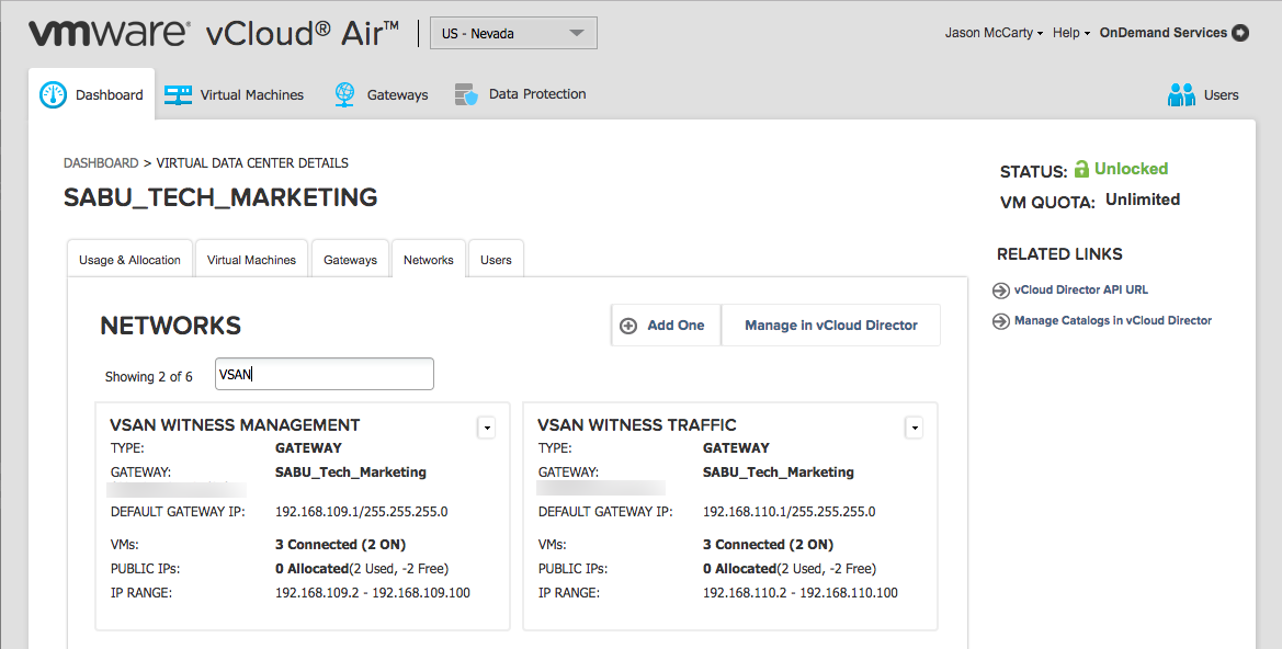
To demonstrate independent networks for each traffic type, management vs. vSAN, two networks can be created from within the vCloud Air interface. Simply chose Add One, and enter the relevant network settings.
As can be seen in the illustration, one will be used for Management Traffic and the other will be used for Witness Traffic.
Firewall Rules
Firewall Rules are important to allow vSAN Witness Appliances to be able to communicate across networks both internal and external to vCloud Air. The networks above are on the 192.168.109.0/24 and 192.168.110.0/24 ranges.
Under the Gateways tab, in the Firewall Rules section, new rules may be added to properly allow for traffic. Four rules are created below, two for each network.
- Management Network – Manage the Witness as a Virtual Host
- Allow-ROBO-IN – The source of traffic is the remote lab network of 192.168.1.0/24, destined for the vSAN Witness Appliance’s management interface (vmk0)
- Allow-VCA-OUT – The source of traffic is from the Witness Appliance’s management interface, destined for the vCenter server managing the Witness Appliance as a host.
- vSAN Traffic Network – Metadata updates
- Allow-ROBO-WIT-IN – Allow traffic to the Witness Appliance vSAN tagged interface from data nodes at a ROBO site.
- Allow-VCA-WIT-OUT – Allow traffic to the Data Nodes interfaces for metadata traffic from the Witness Appliance.
These could be normal vSAN tagged interfaces or witness tagged interfaces when using Witness Traffic Separation.
*Notice in the illustration, for the purpose of this post, all protocols/ports were allowed between networks to quickly deploy the network and ease configuration. In production, the minimum requirement for ports an protocols for vSphere and vSAN need to be put in place. These ports can easily be found in KB Article 1012382.
**Also notice that the Allow-VCA-OUT and Allow-VCA-WIT-OUT rules allow for any destination. While these could be locked down to only the ROBO lab site, they have been purposefully allowed access out to the Internet as well. That is because these rules are being used for some other testing that is unrelated.
IPSec VPN Setup in vCloud Air
The next portion of the configuration requires using the vCloud Director interface. Clicking Manage Advanced Gateway Settings will launch a different interface depending on whether the vCloud Air instance has basic or advanced networking as the default. Again, this post will cover basic networking.
Additionally, in this post, only a single IPSec VPN will be configured for my 2 Node vSAN instance. In a Stretched Cluster configuration that is located in 2 different sites, an IPSec VPN will be required to each individual site.
When using advanced networking, the interface will show the gateway services. Using basic networking, we’ll need to go into Edge Gateway Services to perform some of the next steps.
Configuring DHCP will make it easy to get our the vSAN Witness Appliance upon initial boot up. The DHCP tab is where this is setup.
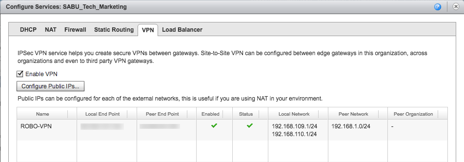
Next, to configure one or more IPSec VPNs, select the VPN tab.
Setting up a VPN from within vCloud Air is pretty straight forward, provided all the addresses/settings are correct.
A name is required, and it is a good practice to include a description.
The Establish VPN to setting allows us to setup a VPN internally within vCloud Air, or to an external IPSEC VPN remote network. Because the ROBO site will not be in vCloud Air, a remote network is chosen.
The two networks created earlier vSAN Witness Management and vSAN Witness Traffic are going to be included in this multi-tunnel IPSec VPN.
In the example to the right, I setup a single peer network (192.168.1.0/24), because I wanted to keep the lab simple. Multiple networks can be configured on both sides of the VPN. If adding a second network to the peer network, be sure to include appropriate firewall rules.
The Local ID is the external IP for the vCloud Air edge gateway (that’s how we’re exiting vCloud Air and getting to the ROBO site/lab.
The Peer ID is the external IP for the ROBO site/lab, and the Peer IP could possibly be different. The Peer IP happens to be the same as the Peer ID in this case because the ROBO site has a router that allows for IPSec VPN capability. The VPN is between vCloud Air and the ROBO site segment of 192.168.1.0/24.
If another appliance or VPN appliance were behind the ROBO site router, the Peer ID would b the external IP, and Peer IP would be the IP of the appliance.
Several different encryption algorithms are available, and I chose AES-256 in this case. Make sure to write down the Shared Key, and take note of the MTU setting.
More detailed info on how to setup a VPN can be found in KB Article 2051370.
ROBO Site Configuration
Setting up the IPSec VPN in vCloud Air is half of the task of getting networking properly configured.
Different solutions are going to have different settings when it comes to setting up a VPN with vCloud Air. Because of this, I won’t go into significant detail on the setup in this post.
It is important though, to remember to configure firewall rules, any Network Address Translations (if necessary), and have all necessary ports open.
While it isn’t necessary to have a single segment on the remote side, it is possible. A single segment can make things easy and dispenses with the requirement of the use of things like a Virtual Tunnel Interface (vti) in the configuration.
Here are a few external links that might provide some guidance on how to configure different solutions to connect with an IPSec VPN to vCloud Air:
- VMware KBTV – More detail
- Not supported by VMware
Also ensure the IPSec VPN configuration includes settings to handle dead peer detection or other mechanism to bring the VPN up in the event it were to go down.
I’ll post some content on the VyOS based configuration I used a little bit later.
Connected
Once the vCloud Air VPN is properly communicating with the remote site, everything should show green.
When deploying 2 Node vSAN clusters, a single VPN connection will likely be the only one required.
When deploying Stretched Clusters across sites, it is necessary to create another VPN to the secondary site.
While not addressed in this post, Static Routing may be required to ensure that traffic from the Witness Appliance to each site only uses the appropriate VPN.
More information on Stretched Cluster Witness routing can be found in the Stretched Cluster and 2 Node guide.
Summary
Now that a working connection is in place, the Witness Appliance can be deployed, configured. Once complete, it can be added to a vSAN 2 Node or Stretched Cluster configuration. Proper networking is required to allow the vSAN Witness Appliance to communicate with 2 Node or Stretched Cluster configurations.
In Part 4, we’ll cover deploying the Witness Appliance from the vCloud Air Catalog that we covered in Part 2.
Stay Tuned.
This was originally posted on the VMware Virtual Blocks site: https://blogs.vmware.com/virtualblocks/2016/11/16/vsan-witness-in-vca-p3/


